• Welcome to ClassicBroncos! - You are currently viewing the forums as a GUEST. To take advantage of all the site features, please take a moment to register. It's fast, simple and absolutely free. So please join our community today!
    If you have problems registering or can't log into your account, please contact Admin.

another one wire alternator question!!

OP
OP
maxwedge5281

maxwedge5281

Contributor
Jr. Member
Joined
Jun 8, 2019
Messages
143
Loc.
concord, nc
i thought that i had posted my latest attempt. at any rate, i disconnected the cable to the alternator at the fuse block. engine cranked right up and ran fine.
 

66broncoCT

Contributor
Full Member
Joined
Feb 6, 2012
Messages
298
Loc.
Torrington, CT
i checked the voltage at the coil...8v with the switch on...12v engine running at idle.
This isn’t good. It means your bronco still has the resistance wire installed, which your Petronix probably won’t like. You should be reading just over 12 volts key on not running and closer to 14 with it running. The electronic ignition needs full battery voltage to operate correctly.
 

m_m70

Contributor
Sr. Member
Joined
Jun 14, 2001
Messages
1,486
Loc.
Pacifica, CA
i just disconnected the alternator cable at the fuse block. the engine cranked right up and is running fine. the voltmeter showed no charge. so i think whatever i thought was wrong seems to be gone.
does it show a charge when it is hooked up??


i thought that i had posted my latest attempt. at any rate, i disconnected the cable to the alternator at the fuse block. engine cranked right up and ran fine.
you did. Oldtimer was asking the voltage reading is between the two battery terminals with the engine running. This will tell you if your alternator is charging.
 

Oldtimer

Contributor
Jr. Member with Sr. moments
Joined
Feb 4, 2005
Messages
912
Loc.
Sunnyvale, CA
Actually I am wondering if the voltages are the same or different at battery and coil.
Trying to ascertain if the pink resistance wire (ballast resistor) is still active, or has been bypassed.
 
Last edited:
OP
OP
maxwedge5281

maxwedge5281

Contributor
Jr. Member
Joined
Jun 8, 2019
Messages
143
Loc.
concord, nc
yes the alternator is charging when i hooked the alternator cable hooked back to the fuse block. engine ran good with no charge showing on gauge cluster voltmeter with the alternator cable unhooked.
 
OP
OP
maxwedge5281

maxwedge5281

Contributor
Jr. Member
Joined
Jun 8, 2019
Messages
143
Loc.
concord, nc
i believe that i have tried all fixes or tests as recommended. the one test that fails is....with the switch on and the engine not running i only measure 8v at the positive post on the coil.....with the engine running at idle i measure 12v on the positive terminal of the coil. even though the engine cranks right up and runs fine with the alternator disconnected from the ignition system the 8v at switch on not running is still concerning. i find no evidence of a ballast resistor but evidently something is still reducing voltage to the coil. what wire should i look for that has resistance between the ignition on and the positive coil post? the alternator is definitely charging 13.5 to 14 volts and the battery is in very good condition with 12 volts.
 

Oldtimer

Contributor
Jr. Member with Sr. moments
Joined
Feb 4, 2005
Messages
912
Loc.
Sunnyvale, CA
. . . i find no evidence of a ballast resistor but evidently something is still reducing voltage to the coil. what wire should i look for that has resistance between the ignition on and the positive coil post?
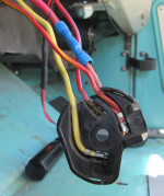
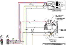
The pink resistance wire and the green/red stripe wire are crimped to the same contact on the ignition switch plug.
At the bulkhead connector the pink wire changes to red/green stripe and continues to coil.
Here is photo of ignition switch connector, where I cut the pink wire, and spliced in a red wire to provide full 12 volts to my ignition system.

1705168462986.png
Interestingly my factory harness has a red/yellow stripe wire in place of the green/red stripe wire usually depicted in schematics?

1705169001990.png
 

DirtDonk

Contributor
Bronco Guru
Joined
Nov 3, 2003
Messages
47,645
On the back of the ignition switch, there is a single position that has two wires coming out of it. One is your green with red wire for the regulator, and the other is either a red with green stripe wire, or a brownish pinkish wire.
Follow the brownish pinkish/ Red with green wire a little ways away from the switch. It should branch off and be in its own harness branch, covered by heat resistant braided sleeving, and possibly even doubled over on itself a couple of times.
That’s your resistor wire.
Follow it up to the firewall and make sure nothing has been spliced in, And then in the engine compartment, check voltage at the red plug.
It’s a three wire plug on the engine side, four wires on the firewall side with the brown wire added.

From the sounds of your results at the coil, as was already said, it sounds like the resistor wire is still there.
The fact that your engine is running fine both with the alternator connected and disconnected, sounds great, and like most of your problems have been solved.
However, if it starts running rough, funky, or not at all, you may need to provide full higher voltage to the coil.
Or at least to the red wire to the distributor.
That’s what the instructions for Pertronix say anyway. If no resistor, you can pull power right off the coil positive like has been done in your case.
If a resistor, then you can still feed the coil from the original wire, but you have to find a more suitable wire to connect a distributor to.
Two options on the instructions, but they are not always clearly readable to the layman.
It looks in the instructions like, no matter what the setup, you can connect the red wire to the coil.
But that’s not the case.
 

DirtDonk

Contributor
Bronco Guru
Joined
Nov 3, 2003
Messages
47,645
Oldtimer is on the job and better, once again.
Pictures and diagrams are always helpful!
 

Oldtimer

Contributor
Jr. Member with Sr. moments
Joined
Feb 4, 2005
Messages
912
Loc.
Sunnyvale, CA
And an easy fix. . .
You went to a one wire alternator, so the external voltage regulator (VR) is no longer needed.
The Green/Red stripe wire from VR plug can be connected to the Brown wire that is on the "I" terminal of the starter relay.
The Brown wire supplys full 12v from starter relay to coil when starting.
By removing Brown wire from relay and connecting to Green/Red wire, the coil will have full 12v when ever key is in run position.

1705171629757.png

1705171667931.png

1705171712444.png
 
OP
OP
maxwedge5281

maxwedge5281

Contributor
Jr. Member
Joined
Jun 8, 2019
Messages
143
Loc.
concord, nc
thanks guys for all the information and you time to post. i think that i will use the brown wire from the solenoid as that seems easier and much more accessible than digging around under the dash. i will post the results one i have done that.
 
OP
OP
maxwedge5281

maxwedge5281

Contributor
Jr. Member
Joined
Jun 8, 2019
Messages
143
Loc.
concord, nc
should i terminate the resistor wire and just use the brown/red green wire combination for the ignition to the coil. and, if so how does the brown/redgreen wire combination by pass the pink resistor wire at the switch?
 

DirtDonk

Contributor
Bronco Guru
Joined
Nov 3, 2003
Messages
47,645
The resistor is not at the switch. It's in the design/size/length of the ugly brown wire.
So just utilizing the Green w/red wire alone is literally bypassing the resistor section of the resistor wire.
Terminating the resistor wire is a good idea. It's still hot with the key in the ON position, so it's just good practice to cap it off, so to speak.

Paul
 

Oldtimer

Contributor
Jr. Member with Sr. moments
Joined
Feb 4, 2005
Messages
912
Loc.
Sunnyvale, CA
The pink resistance wire and GR/RD wire are connected at ignition switch.
The pink wire turns to RD/GR at bulk head connector
RD/GN wire and brown wire are connected to each other at the 3-wire plug (usually red) at back drivers' side of engine.
If you connect GR/RD and brown wires together near starter relay the pink wire is bypassed and is there is not much point in cutting and terminating it.

1705443186262.png


1705441613433.png

As Paul pointed out (while I was typing) terminating the pink resistor wire is not a bad idea, but us old guys are good at becoming a pretzel to get under thedash, so I would leave it alone.
 

DirtDonk

Contributor
Bronco Guru
Joined
Nov 3, 2003
Messages
47,645
Sorry, I probably misread your question and thought that, by "Brown" you meant the resistor wire. Where you probably meant the Brown wire from the starter relay like Oldtimer discerned.
Whether or not you need to cap something off, depends on how you leave it and how (or if) you cut it.

Paul
 
OP
OP
maxwedge5281

maxwedge5281

Contributor
Jr. Member
Joined
Jun 8, 2019
Messages
143
Loc.
concord, nc
thanks guys. im 83 so twisting like a pretzel is something for me to avoid. i believe that satisfies my question. brown at the relay and green/red at the vr and probably cap off the resister wire.
 

ba123

Contributor
Bronco Guru
Joined
Oct 29, 2022
Messages
1,752
Loc.
CA
thanks guys. im 83 so twisting like a pretzel is something for me to avoid. i believe that satisfies my question. brown at the relay and green/red at the vr and probably cap off the resister wire.
Love that you're 83, posting on a forum, and working on a Bronco!!!

Kuddos!
 
OP
OP
maxwedge5281

maxwedge5281

Contributor
Jr. Member
Joined
Jun 8, 2019
Messages
143
Loc.
concord, nc
well i think that i have finally got the wiring as suggested. i clipped the red/green wire at the vr plug and tied it into the brown wire removed from the starter relay. i think that is what was suggested. it did improve voltage with switch on to 10.5 volts at the coil positive post. battery measures a full 12 volts . i did not terminate the resistor wire from the switch. the engine does seem to run better when accelerating through the gears but i do get an occasional pop from the mufflers. with the engine running i measure a full 12v at the coil.
 
Top