• Welcome to ClassicBroncos! - You are currently viewing the forums as a GUEST. To take advantage of all the site features, please take a moment to register. It's fast, simple and absolutely free. So please join our community today!
    If you have problems registering or can't log into your account, please contact Admin.

ARB Compressor Harness Installation

Jeff10

Contributor
Bronco Guru
Joined
Feb 20, 2011
Messages
2,138
Loc.
Indianapolis
Hi Everyone,

Several years ago I had a local shop install the wiring harness and switches for the ARB lockers on the '70 Bronco. There are a few electrical oddities that I'm trying to track down now.

The compressor was physically mounted by another shop prior to the electrical work being done.

I don't have the information on the compressor. I believe I bought it from someone on the forum a number of years ago. Below is a pic of it installed on the driver inner fender.

Without asking a lot of questions that I know will require more detailed information, I thought I would just ask a couple of basic electrical questions.

1. Would this ARB compressor ever be installed without a fuse and power relay? There isn't a relay in the circuit as it is now.

2. The system is wired into one of the switched circuits on the Painless harness. It is not connected to the battery and ground. This is different than I would have expected, and different than the manual states.

3. (The way this is wired now, the power wire from the Painless harness is wired to the two wires on the ARB harness that are for the light illumination power and the ignition power. To me that seems odd.)

Anyway... the main question I have is about power, and if perhaps this compressor (for locker actuation only) would ever be wired properly without the relay, and the direct connection to the battery.

Thanks,

Jeff
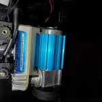
20230815_090535 1920 x 1080 res.jpg
 

nvrstuk

Contributor
Just a Bronco driver for over 50 yrs!
Joined
Jul 31, 2001
Messages
8,794
Hi Everyone,

Several years ago I had a local shop install the wiring harness and switches for the ARB lockers on the '70 Bronco. There are a few electrical oddities that I'm trying to track down now.

The compressor was physically mounted by another shop prior to the electrical work being done.

I don't have the information on the compressor. I believe I bought it from someone on the forum a number of years ago. Below is a pic of it installed on the driver inner fender.

Without asking a lot of questions that I know will require more detailed information, I thought I would just ask a couple of basic electrical questions.

1. Would this ARB compressor ever be installed without a fuse and power relay? There isn't a relay in the circuit as it is now.

2. The system is wired into one of the switched circuits on the Painless harness. It is not connected to the battery and ground. This is different than I would have expected, and different than the manual states.

3. (The way this is wired now, the power wire from the Painless harness is wired to the two wires on the ARB harness that are for the light illumination power and the ignition power. To me that seems odd.)

Anyway... the main question I have is about power, and if perhaps this compressor (for locker actuation only) would ever be wired properly without the relay, and the direct connection to the battery.

Thanks,

Jeff
View attachment 908163
1- no

2- Check the ARB online wiring diagram. I would think that the Painless harness circuit would not be high enough amperage to carry the load. Usually the single pump pulls appr 30amp load. What does the ARB schematic say?

3- Sounds like all the painless harness connection is doing is lighting up the "light illumination" (I don't know what that is or what it's purpose is other than to show that it is in the "on" mode and then the ignition power wire turns the unit off and on but the compressor needs an appr 30 amp circuit connected to it.

Anyway- it needs a large wire connected directly to the + battery from the compressor with a appr 30 amp (again, look at the wiring diagram). Then of course it needs a large ground wire connected directly to the battery also. The small wires you are talking about seem to be the "switching" wires which carry very low current and shut the unit off and on.

Switch for the actual ARB is of another answer.
 
OP
OP
Jeff10

Jeff10

Contributor
Bronco Guru
Joined
Feb 20, 2011
Messages
2,138
Loc.
Indianapolis
nvrstuk,

I asked the question because I don't have the manual. I can't tell from the installed compressor what the model information is for that unit. I was merely asking in a general sense about the power relay and if possibly I was misunderstanding that this is a smaller compressor that may not require it.

Nothing I like better than paying a shop to do something that has to be redone after troubleshooting why it won't work.

I'll pull the compressor out so that I can see the model information, look up the proper manual and do this the way I should have done it before posting here.

Jeff
 

Broncobowsher

Total hack
Joined
Jun 4, 2002
Messages
34,948
I believe that is the smallest of the ARB compressors. That is what I have on my boat for an air horn. Fine for small stuff (lockers, air horns), but not useful for airing up tires. Unlike the bigger ARB compressors, this one is NOT 100% duty cycle. I think it is only 50% duty cycle.

Just checked my boat. No relay. Just power to the pressure switch and the pressure switch directly powers the compressor. And that is how I got mine directly from ARB. The amp draw isn't very high, again this is not a high output air compressor. The amp meter on the boat only shows a few amps while it is running, less than the bilge blower fans.

So long as the circuit feeding the compressor is fused, it should be good. No direct to the battery, no relays.

And the bolt at the back of the motor (top of your picture) looks to be a couple turns loose. Grab your metric wrenches to fix that one. Pretty sure you will need a 10mm.
 

nvrstuk

Contributor
Just a Bronco driver for over 50 yrs!
Joined
Jul 31, 2001
Messages
8,794
Bowsher - good info.

That thing must be tiny.

Even the 1st Gen ARB compressors from '86 drew 10+ amps as I had one for my ARB in Feb '87.

Good info
 
OP
OP
Jeff10

Jeff10

Contributor
Bronco Guru
Joined
Feb 20, 2011
Messages
2,138
Loc.
Indianapolis
Hey Broncobowsher,

Thanks for checking. Thanks for the bolt observation, too.

I am going to pull the compressor just so I can read the model number. (I may have been given some of the manuals by the shops working on the Bronco. I'll see if I can find anything there, too.)

I appreciate the thoughts.

Jeff
 

rocknhorse76

Contributor
Bronco owner since 1993 💪🏻
Joined
Jun 7, 2014
Messages
366
Loc.
Central WA

Here’s the manual for that compressor. The red/yellow wire goes to a switched and fused 15A circuit. The switched accessory wire from your Painless harness should be fine. Black goes to battery (or GOOD chassis) ground. Blue/white wire goes to the dash illumination wire (basically the wire that runs your dash lights). That allows your switches to light up when your headlights and dash lights are on. No relay is required since it’s a pretty small current draw. I believe the compressor only pulls like 5.5A with no load on it.
 
OP
OP
Jeff10

Jeff10

Contributor
Bronco Guru
Joined
Feb 20, 2011
Messages
2,138
Loc.
Indianapolis
Rock horse,

Thank you. I found the manual at Quadratec, too. I was going to post the diagram here yesterday. I had to leave town for a funeral. I will do that this weekend. I appreciate all the detail.

Jeff
 
OP
OP
Jeff10

Jeff10

Contributor
Bronco Guru
Joined
Feb 20, 2011
Messages
2,138
Loc.
Indianapolis
Hey Again,

In attempting to troubleshoot the compressor and locker wiring I found that the switches for the front and rear locker are 4-pole switches. In the wiring diagram the switches are shown to be 5-pole.

I have some switches from previous builds that are 6-pole; but, they are 3-position rockers.

I have been looking for information online about the internal configuration of the switches; but, I'm not having much luck. ARB's site isn't particularly user friendly.

I have been looking at replacement switches (180223SP and 180224SP) but I can't confirm that they are 5-pole switches.

Does anyone have experience with these switches?

Thanks,

Jeff
 

Broncobowsher

Total hack
Joined
Jun 4, 2002
Messages
34,948
The number of connections is irrelevant, function matters.
You don't have 4,5,or 6 pole switches. Pole represents the branch inside the switch.
The most basic switch, just on/off, is a single pole single throw switch. Has 2 wires going to it.
If you put 2 of these switches side by side (inside a single housing, controlled by a single lever) it would be a 2 pole single throw switch. 4 wires going to it.
If you take a switch and have a common wire that switches between 2 connections, that is a single pole 2 throw switch. 3 wires go to it.
A real common switch is a 2 pole 2 throw switch. That has 2 separate switches inside a single housing, each switch will connect the common to its corresponding matched terminals.
The poles and throws are abbreviated. 2P2T switch is a 2 pole 2 throw throw switch (6-wires). The can add center off as a side comment, but that doesn't add an extra throw to the count. SPST uses S for single instead of a number, this is a basic 2-wire on/off switch.

Those ARB switches also add lights. Those are even more wires. Some switches will add the light to the switch so all you need to do is add a ground. That would be the cheap accessory switches that are simple on/off (SPST), but have a 3rd wire. That third wire is the ground for the light bulb. Power for the light bulb is internal to the switch. ARB switches don't do that, the light power and ground are separate from the switched contacts. Essentially just a random light bulb that happens to be in the same housing as the switch. Go a step further as there is another light for dashboard illumination

So the ARB switches are numbered. The switches can be had for other applications, they are not ARB specific, just what ARB uses.
2 is power in
3 is switched power out.
These two alone are the basic switch function
6 is the illumination so you can see the switch at night.
7 is the ground for the illumination
these two are just so you can find the switch at night. basicly a random light bulb that has nothing to do with the switch itself.
8 is another ground. This goes back to the cheap parts store lighted switch. The other half of this light bulb (the power side) is connected internally to post #3

The only thing needed to make the ARB switch actually switch, is post 2 and 3. The rest are just for light bulbs.

You say you have 4 pole switches. From you calling the above wiring diagram a 5 pole switch, I know you really don't have a 4 pole switch. You probably have a switch that has 4 wires on it. And that is only a guess off an improper description and trying to translate it. I really can't answer what that switch is. I would guess it is probably correct, maybe it has a light in it? As for randomly splicing in a DPDT switch (what I am pretty sure you are calling a 6-pole switch) will probably result in short circuits. So not knowing what you have, can't give instructions to adapt to the new switches you have.


Reading everything again, it sounds like there was a quick shortcut made, or maybe a redesigned switch that no longer uses a seperate illumination wire and just uses the accessory wire. If that is the case the wiring is the same as the 5-wire ARB switch, just pins 2 and 7 are spliced together. Maybe externally, maybe internally. Not knowing what your 4-wire switch looks like, and functions like, can't answer that for you.
 
OP
OP
Jeff10

Jeff10

Contributor
Bronco Guru
Joined
Feb 20, 2011
Messages
2,138
Loc.
Indianapolis
Broncobowsher,

My apologies. In writing my message I used the wrong term.

The diagram for this compressor shows 5-pin switches for each of the lockers. The two switches that were installed are 4-pin.

I don't know why the compressor and lockers are wired the way they are wired.

I can't attest to whether the switches are ARB, or ones meant to resemble ARB. I also don't know the details of the switch internals.

I'm just trying to work through this...

Jeff
 

Broncobowsher

Total hack
Joined
Jun 4, 2002
Messages
34,948
We will need more information on the 4-pin switches you have. They don't match any documentation we have. That is the mystery we have any you have the pieces.
Pictures (front and back) would be the best starting point.
 
OP
OP
Jeff10

Jeff10

Contributor
Bronco Guru
Joined
Feb 20, 2011
Messages
2,138
Loc.
Indianapolis
Hey Again,

Well... not sure where the 4-pin switches came from. Based on the switch covers I suspect that they are from Yukon Gear; but, I haven't been able to find any useful information about the number of pins or a schematic for them. In the overall scheme of things it's not so important now.

I ordered new ARB replacement, 5-pin switches that should be here by mid-week. I looked at several different schematics for various compressors/lockers that ARB sells. All of the ones that I saw were 5-pin switches.

So... we'll do this right and I'll be able to ask more intelligent questions. lol

Thanks,

Jeff
 
OP
OP
Jeff10

Jeff10

Contributor
Bronco Guru
Joined
Feb 20, 2011
Messages
2,138
Loc.
Indianapolis
Hey,

Update... Two of the new 5-pin switches arrived yesterday. One of the original switches was 5-pin, too. So, until the correct switch arrives this one will work.

All the system components are now wired per the manual rocknhorse76 linked. The system operates the lockers, too.

The system works as it should. (For some reason the original 5-pin switch that was used lights the LED even with the headlights off. That shouldn't an issue when the new switch is installed.)

I appreciate all the advice.

Jeff
 
Top