• Welcome to ClassicBroncos! - You are currently viewing the forums as a GUEST. To take advantage of all the site features, please take a moment to register. It's fast, simple and absolutely free. So please join our community today!
    If you have problems registering or can't log into your account, please contact Admin.

'70 LUBR Build

OP
OP
5

5_oh_bronco

Jr. Member
Joined
Nov 10, 2014
Messages
64
Loc.
Grand Junction
Question about your front brakes 5_oh. How hard did you have to hammer the sliders/anchors in to get them to fit?

Paul,
If I recall, I did a little more than just "tap" the sliders in. I figured that it was designed to preload the caliper a little so that it wouldn't knock when stepping on the brakes. Well, perhaps I'll pull them apart, sand a few thousands of an inch off to loosen them up just a smidge, then reassemble them.

Thanks for the tips on the steering, too. As it turns out, a little luck came my way. I was talking with a local bronco buddy the other day, and we got to doing some horse trading, and I ended up with a stock PS steering box! The only thing about it that I don't love is that it is 5-3/4 turns lock to lock. Wow! But I guess that's part of the fun of driving an old truck: Just keep turning the steering wheel, and eventually, you'll turn the corner!
 

DirtDonk

Contributor
Bronco Guru
Joined
Nov 3, 2003
Messages
47,649
Yeah, some people like that old feel, but most prefer the '76 and later steering that's more in the 4 to 4.5 lock-to-lock range.
And when we have stock ones rebuilt now, we simply convert them to the later faster steering since that's what most prefer.

Good idea to check the brakes then. Sounds like they might be tight enough to give you some trouble. With the pressures exerted, the caliper will likely still slide unless those buggers were really jammed up in there.
It's a good design actually, but prone to sticking due to rust (lack of maintenance actually) and other things.
Even though yours look super clean and flat in the pics, I always dress down the sliding surfaces with a file and lube them with anti-seize. Wouldn't hurt for you to do the same.
Even though your paint looks excellent and thin enough, maybe it's still adding to an already tight fitting component.

I can't see in your pics, but it almost looks like the spring thingy is in upside down. Probably not, since it's super hard to install them that way (well, you did say it took some persuasion!) but the leaf spring should be "hump up" with the ears on the end facing down over the sliding bar.
Is that how yours are?

Paul
 
OP
OP
5

5_oh_bronco

Jr. Member
Joined
Nov 10, 2014
Messages
64
Loc.
Grand Junction
Even though yours look super clean and flat in the pics, I always dress down the sliding surfaces with a file and lube them with anti-seize. Wouldn't hurt for you to do the same.
Even though your paint looks excellent and thin enough, maybe it's still adding to an already tight fitting component.

I can't see in your pics, but it almost looks like the spring thingy is in upside down. Probably not, since it's super hard to install them that way (well, you did say it took some persuasion!) but the leaf spring should be "hump up" with the ears on the end facing down over the sliding bar.
Is that how yours are?

Paul

Looks like I'll be pulling my brakes apart to check the fit, and make sure the leaf springs are installed correctly. I just checked my pictures, and I can't quite tell either!
 
OP
OP
5

5_oh_bronco

Jr. Member
Joined
Nov 10, 2014
Messages
64
Loc.
Grand Junction
So based on some very helpful tips from a seasoned bronco guru (DirtDonk), I realized that I needed to pull the front brakes apart and reassemble the caliper to the bracket.

As you can see from the pictures below, I obviously had not assembled the weird slider thingy/leaf spring combo correctly. When I assembled it the first time (incorrectly), I was surprised at how tight everything seem. Go figure.

For a better understanding of my mistake, take a look at the second and third pictures.

In the picture called Leaf_position_1, you can see where I had put the leaf spring the first time around: between the slider thingy and the bracket. The picture called Leaf_position_2 shows where I believe the leaf spring is supposed to go, between the slider thingy and the caliper.

Well, I made the switcheroo this morning, and I immediately noticed that it only required light tapping with the hammer to push the slider thingy/leaf spring combo into place. Also, once reassembled, I could actually move the caliper a little by hand. Much better!

Thanks, Paul!
 

Attachments

  • Brake_slider_thing_wrong.jpg
    Brake_slider_thing_wrong.jpg
    155.8 KB · Views: 64
  • Leaf_position_1.jpg
    Leaf_position_1.jpg
    161.7 KB · Views: 60
  • Leaf_position_2.jpg
    Leaf_position_2.jpg
    151.3 KB · Views: 59

DirtDonk

Contributor
Bronco Guru
Joined
Nov 3, 2003
Messages
47,649
A result! As Edd would say.
It's all about communication. If you hadn't mentioned how hard it was to install, I wouldn't have known the right question to ask.
And hey, you're probably one of only a handful of people that have figured out how to install that little springy-clippy-noise-reducer-thingy that even seasoned veterans have to figure out each time!

Glad it felt better going together this time.

Paul
 
OP
OP
5

5_oh_bronco

Jr. Member
Joined
Nov 10, 2014
Messages
64
Loc.
Grand Junction
Well, it seems I've let my build thread lapse for a bit again. It's always tough to squeeze build time in a day, let alone time to take pictures and write about it!

Despite another couple of trips out of town for work, I've managed to get a little work done on the build.

Since the chassis work is just about done, I decided to set the body on the frame again to check for clearances, get the radiator and brake booster mounted, and check the location of the tailpipes relative to the body.

All in all, I am quite pleased with how everything turned out. There are only a couple of tight spots that will require some attention. The bracket to which the e-brake cables mount hits the top of the driver's side muffler. This should be easily remedied by either cutting a little scallop out of the bracket, or simply shortening the bracket. The other tight spot is at the passenger side exhaust flange, which just bumps the inner fender. This should also be an easy fix, as all that should be required will be to move the inner fender wall by about 1/2".

The good news is, despite the Mustang 5.0 EFI and 5 spd conversions, the body will mount just fine with no body lift!
 

Attachments

  • muffler_interference.jpg
    muffler_interference.jpg
    208.6 KB · Views: 50
  • exhaust_interference.jpg
    exhaust_interference.jpg
    215.9 KB · Views: 49

englewoodcowboy

Lick Creek Restorations
Joined
Jul 25, 2010
Messages
4,200
I would highly recommend running a 1" body lift. It will provide the clearance you need with no cutting and you will thank yourself down the road if you ever have to work on the trans or T case. 1" is not much but the room it gains around the T case and trans is huge... Specially when pulling or reinstalling the cross member, linkage etc. Just my $.02. I know you are wanting to minimize lift to keep it mostly stock but after helping Blue71 work on one of his broncos and we had to drop the T case twice... Needless to say I am very glad I opted for the 1".
 
Last edited:
OP
OP
5

5_oh_bronco

Jr. Member
Joined
Nov 10, 2014
Messages
64
Loc.
Grand Junction
To Lift or not to Lift?

Regarding the body lift:

Most likely, you guys are absolutely correct about adding 1" of body lift. With the tub sitting on the frame right now, there really isn't much clearance around the T-case (particularly at the tail end of it). I'm not sure what it is in me (maybe the engineer?) but I've always got to do things the hard way!

There are a couple things that I did when, A: fabricating my new cross-member, and B: working on the body to address the clearance issue.

A: On my new cross-member installation, I actually flipped the L-brackets that bolt to the frame to gain additional clearance underneath the cross-member. The cross-member then sits on a little stack comprised of steel and urethane mounts. If it is necessary to pull the tranny at some point in the future, I can pull the mount bolts, pull the stack out, and immediately drop the tranny by about 2" or so just for additional working room.

B: On the body; I added about 1" of additional clearance to the transmission tunnel. Where the firewall comes down and meets the horizontal piece of sheet metal through which the shifters come up, I added one additional angled step. I cut the sheet metal and body stiffener that run directly underneath this area, and tucked the body stiffener up against my new angled piece of sheet metal. Check out the pictures below.

Of course, this isn't any sort of guarantee that this "no body lift" thing won't come back and bite me! Then I'll have to write a post so that you guys can say, "Told you so!"
 

Attachments

  • x-member_pass.jpg
    x-member_pass.jpg
    173.7 KB · Views: 39
  • modified_tunnel2.jpg
    modified_tunnel2.jpg
    155.3 KB · Views: 32
OP
OP
5

5_oh_bronco

Jr. Member
Joined
Nov 10, 2014
Messages
64
Loc.
Grand Junction
Recently, I've remounted the tub to the frame and have been working on a few details related to the body that will require a little more fab. This includes primarily: mounting the mustang radiator, relocating the battery tray, providing clearance for the exhaust, and mounting the hydroboost for the new power disc brakes!

I've decided to go with the mustang radiator for a few reasons. First, it is obviously a good match for the engine (good job 90's Ford engineer guys) and has greater cooling capacity than the stock Bronco radiator. The mustang engine makes considerably more power than the stock 302, and more power always equals more heat! Secondly, it is lighter than the stock Bronco radiator, being all aluminum. Lastly, since I am using a completely stock wiring harness for my mustang 5.0, it is convenient to be able to connect directly to the electric fan and coolant level sensors already in place.

There have been a few challenges, however, in mounting it. The challenge that I seriously did not expect was that it is too tall! I pulled the radiator out of the front of a mustang, which is a relatively low profile "sports" car and went to put it in the front end of a truck. The last thing I expected was for it to be too tall. Go figure. Part of the issue is that it is considerably wider than the stock radiator and does not fit down between the frame rails.

Fitting it in took a few modifications of the body. First, to clear the power steering box, the radiator has to slide toward the passenger side. This invades the stock body mount and battery tray locations. Out came the original body mount. (and good thing too, since I found a little more rust!) Fixing this required the fabrication of a custom body mount which replaces some suspiciously thin sheet metal on the inner fender, replaces and relocates the stiffener between the inner fender and the core support, provides the actual body mount, and provides and recessed pocket for holding the radiator. A little work with a Sharpie, some 14 gage steel, 4-1/2" angle grinder, a MIG welder, and Presto! New body mount!

With the new body mount in place, the radiator dropped right in quite nicely and fits under the hood with plenty of clearance. As an added bonus, the stock mustang coolant reservoir also drops in with plenty of clearance, sitting just inside the passenger frame rail.

I know, I know... a body lift would have made this process easier too. But where is the fun in easy?
 

Attachments

  • new_body_mnt2.jpg
    new_body_mnt2.jpg
    212.2 KB · Views: 45
  • new_body_mnt1.jpg
    new_body_mnt1.jpg
    168.5 KB · Views: 45
  • rusty_body_mnt2.jpg
    rusty_body_mnt2.jpg
    176.5 KB · Views: 42
  • rusty_body_mnt1.jpg
    rusty_body_mnt1.jpg
    219.2 KB · Views: 44
  • new_body_mnt3.jpg
    new_body_mnt3.jpg
    218.9 KB · Views: 48
  • radiator_test_fit2.jpg
    radiator_test_fit2.jpg
    287.7 KB · Views: 44
  • body-radiator_mnt.jpg
    body-radiator_mnt.jpg
    222.7 KB · Views: 48
  • radiator_resevoir.jpg
    radiator_resevoir.jpg
    193.8 KB · Views: 50
  • radiator_clearance.jpg
    radiator_clearance.jpg
    178.4 KB · Views: 52
OP
OP
5

5_oh_bronco

Jr. Member
Joined
Nov 10, 2014
Messages
64
Loc.
Grand Junction
The work to get all the little interference and mounting issues with the body worked out continues...

This week I ended up replacing a bit of the core support. In the previous post, I showed pictures of the new body mount that I fabricated for the passenger side at the core support. This time, it was the driver side that needed some attention. In an attempt to get every millimeter of clearance that I can between the engine and the firewall, I pushed the body rearward and discovered that the core support was hitting the front of the power steering box. A bronco buddy of mine here in town was showing me how little clearance there is between the power steering box and the core support even on broncos that came from the factory with the power steering.
On my bronco, this situation was even further exacerbated by the fact that the core support panel immediately in front of the power steering box was bent toward the box from some badness that happened long ago. The stories an old vehicle will tell when you dig into it are always intriguing!
After doing a little head scratching (and beer swigging), I decided the best course of action was to cut the bent panel out and replace it. I figured this would be easier that trying to straighten the kinks out. A few minutes work with the 4-1/2 inch angle grinder set up with a zip disk, and the bent panel was lying on the floor!
Fabricating the new panel was about as easy as could be (with the proper tools, that is). I used a 1-1/2 inch hole saw to cut a hole in the new panel for the blinker wire, sized, cut, and welded in the panel. To pick up a little extra space between the new panel and the steering box, I actually welded the panel to the front side of the core support. This moved the new panel about 1/8 to 3/16 inches forward compared to the original panel.
Next project is to get the hydraboost and pedals mounted.
 

jmangi62

Bronco Guru
Joined
Jul 28, 2013
Messages
2,469
Looks like things are going together pretty good,may I just say that I have the WildHorses 1" body lift and you can hardly notice it,many guys on here run it and will suggest it to you,so if you ever feel the need to get it,just get it from WH.Nice build by the way! ;D:D
 
OP
OP
5

5_oh_bronco

Jr. Member
Joined
Nov 10, 2014
Messages
64
Loc.
Grand Junction
For all you guys running the 1" body lift: Do you use the factory shift cover/indicator for the transfer case stick? I really want to use the stock unit, as I want the interior to look as close to stock as possible, but I noticed that if the tranny/t-case sits even just a little too low, the little indicator lines don't line up correctly with the 2wd, 4 Hi, Nuetral, and 4 Lo marks on the cover. Also, when trying to shift into either 4 Hi or 4 Lo, the stick actually ran into the ends of the slot on the cover.
 

DirtDonk

Contributor
Bronco Guru
Joined
Nov 3, 2003
Messages
47,649
While I don't think it happens on all Broncos, it's pretty common for the shift indicator not to line up anymore. Less common to run out of room in the slot on the floor, but happens also. As in your case apparently.
I can't say for "most" but I would say that at least "many" EB's are sporting some sort of simple boot arrangement nowadays. Even before the installation of body lifts, many will either lose their stock one during a restore/resale, or break it during normal use or maintenance, replace the shifter with something else so the stock one does not fit, or just remove it because they don't like it.

So lots of body lift installers never run into the issue you're having.
We just discussed it recently here and it was kind of left up in the air as to what the best way to proceed is. Not sure if anyone has actually fixed one up so that it worked properly.

Sorry for the bad news for your stock-as-possible build. The subject just hasn't come up all that often here to have a lot of solutions.
We talk about clutch rods, column shift linkages and radiator shrouds all the time. Even parking brake cables now and then. But hardly ever (until more recently) does the t-case subject come up.
Even in the instructions it's kind of basic. Just a mention that you "might" have to make the hole in the floor bigger. And even that's more often for the 2" and up crowd. One of the reasons for the 1" is that it's not as detrimental to that kind of thing.

Sorry we didn't make a bigger deal of it before you started your project. Not that the 1-incher is any less of a good idea for an EB, but it might have given you more of an idea what you were up against in your desire to keep things stock.

Good luck!

Paul
 
OP
OP
5

5_oh_bronco

Jr. Member
Joined
Nov 10, 2014
Messages
64
Loc.
Grand Junction
Paul,
Thanks for the info! Well, it certainly isn't possible to predict all of the challenges one may encounter when jumping into a build like this! Besides, without a few things here and there to make one scratch their head, what fun would it be?

The 1" body certainly does seem to make sense, and I haven't yet ruled it out. However, as I've been going along on the build, I've been planning not to do the body lift. So far, the issues I've run into, and the solutions I've come up with are as follows:

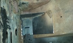
1. The mustang tranny (WC T5) is slightly taller than the original 3 speed, by about 3/4", and was just barely hitting the body stiffening cross member at the front of the transmission tunnel.
Solution: I cut a patch out of the tunnel where the horizontal surface (thru which the shifters come up) meets the angled portion at the front, added a new panel that is angled slightly upward, and adds about an extra 1" of clearance between the tranny and tunnel.
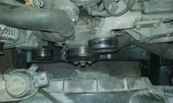
2. The mustang radiator does not sit down between the frame rails like the original did. (this actually would not be remedied by a body lift)
Solution: I built a custom body mount for the passenger side that incorporates a recessed mount for the radiator to sit down into.
3. The bracket for the front end of the e-brake cables hits the top of the driver side muffler by about a 1/4".
Solution: I shortened the bracket by about 1/2" and cut a semicircular notch to provide clearance. I think I will also use this bracket to help hold a heat shield.
4. The monstrous intake manifold on the 5.0 obscures the hole through which the original throttle linkages passed.
Solution: I am actually using the mustang throttle cable (as suggested by other forums here at www.classicbroncos.com). I made a small patch panel with the proper holes to mount the mustang throttle cable. I made the patch panel large enough to cover the original openings in the firewall for the original throttle linkage, then cut the firewall and welded in the new patch panel.
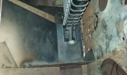
5. My custom tranny adapter designed and fabricated to mount the Dana 20 to the WC T5, which also mounts the t-case shifter and houses the shift gate and shifter for the tranny, moved the t-case rearward by about 1/2", causing some tight clearances between body and t-case.
Solution: While there was enough clearance for the t-case even when sitting at the correct height, I was concerned about room to get at bolts and move stuff around if ever I should need to drop the tranny. So I flipped the L-brackets to which the cross-member mounts, then added shims between the mounts and the cross-member to get the t-case to the correct height. Also, I use a single, long bolt on each side to mount the cross-member. These bolts are oriented with their head on the lower side, and the nut (castle nut with cotter pin) on the top side. This allows the bolt to be pulled out from the underside, avoiding interference with the body.

Anyhow, like I said, I haven't ruled out the 1" body lift yet. I need to think about what it gains me, and how to solve the stock t-case shift indicator issue!
 
OP
OP
5

5_oh_bronco

Jr. Member
Joined
Nov 10, 2014
Messages
64
Loc.
Grand Junction
While I don't think it happens on all Broncos, it's pretty common for the shift indicator not to line up anymore...

...So lots of body lift installers never run into the issue you're having.
We just discussed it recently here and it was kind of left up in the air as to what the best way to proceed is. Not sure if anyone has actually fixed one up so that it worked properly.

Sorry for the bad news for your stock-as-possible build. The subject just hasn't come up all that often here to have a lot of solutions.
We talk about clutch rods, column shift linkages and radiator shrouds all the time. Even parking brake cables now and then. But hardly ever (until more recently) does the t-case subject come up.
Even in the instructions it's kind of basic. Just a mention that you "might" have to make the hole in the floor bigger. And even that's more often for the 2" and up crowd. One of the reasons for the 1" is that it's not as detrimental to that kind of thing.

Good luck!

Paul

Paul,
It's been a couple of weeks since this subject was discussed, but shortly after you posted the comment above about discussing it at WH, I had an idea that might work.
The concept would include replacing the T-case shift stick, position lock bracket (little plate with the slots that locks the T-case shifter in position) and pivot bolt with new pieces. The pivot bolt and position lock bracket would both be replaced by a single piece that would include a thicker position lock bracket to which would be welded two threaded studs: one which would pass through the hole on the T-case adapter (mounting the plate to the adapter) and one on which the new T-case shifter would pivot. These two studs would be offset so as to raise the pivot point (toward the body). The effect would be to shorten the throw of the T-case shifter. The added shifting effort would be negated by increasing the length of the shifter so as to make the shifter stick out of the floor by the same amount as it did with a stock body height. i.e. a 3" body lift would require a shifter 3" longer than stock.
I'll see if I can quickly model something up in CAD and post it so you can get a visual.
 
OP
OP
5

5_oh_bronco

Jr. Member
Joined
Nov 10, 2014
Messages
64
Loc.
Grand Junction
Here are a couple pictures of the bracket I am envisioning and was trying to describe in the post above. It isn't modeled perfectly, but I think it gets the idea across. I would have to do the math to calculate the proper ratio of pivot offset/body lift to keep the stock shift boot working correctly.
 

Attachments

  • Body_lift_position_lock_bkt_1.JPG
    Body_lift_position_lock_bkt_1.JPG
    25.5 KB · Views: 5
  • Body_lift_position_lock_bkt_2.JPG
    Body_lift_position_lock_bkt_2.JPG
    28.6 KB · Views: 6

sprdv1

Contributor
REBEL
Joined
Mar 8, 2007
Messages
81,756
Well, it seems I've let my build thread lapse for a bit again. It's always tough to squeeze build time in a day, let alone time to take pictures and write about it!

he good news is, despite the Mustang 5.0 EFI and 5 spd conversions, the body will mount just fine with no body lift!


Gotta do what you can when you can. Hang in there brother
 

DirtDonk

Contributor
Bronco Guru
Joined
Nov 3, 2003
Messages
47,649
Seems like a great idea if all the new bits work together.
My geometry is rusty for sure, so I'll trust your numbers. But what about the necessarily lengthened lower part of the shift lever? Would the same length as stock still push the rod and equalizer bar at a correct enough angle, or would that part of the arm need to be lengthened by the same amount as the lifted lock bracket?
If you have to lengthen the lower half, what does that do to leverage AND travel? Seems like it would shorten the travel a bit on it's own, but that might be a good thing.

Interesting and simple idea. Does your CAD program (or your brain!) give numbers on what those changes in lengths do to shifter travel?
And do you think you would need to lengthen the lower half (below the pivot point) more, or could leave it near stock and have it still work the shift rods?

Maybe it's a non-issue. I'm just going from memory and don't have (even with my work resources!) a stock setup sitting handy to look at.

Paul
 
OP
OP
5

5_oh_bronco

Jr. Member
Joined
Nov 10, 2014
Messages
64
Loc.
Grand Junction
Paul,

Maybe we should split this off into a new thread? (Not sure how to do that!) You are spot on with your questions.
What I didn't draw up was a new shift lever. The new shift lever would require a longer lower portion to keep the angles correct for the short rod and equalizer bar. Having that longer lower section does two things:
1. It decreases the total travel of the shift lever needed to make the correct shifts, and
2. It does change the leverage.
Point number 1 accomplishes the goal of keeping the travel correct for the stock shift boot to work, pointers line up, etc...
By making the shift lever longer on the top side as well, you gain some of that leverage back.

I didn't check any numbers when made that model this morning. It was just a proof of concept thing. I would have to look at the actual stock geometry to get real numbers. My guess is that for, say a 2" body lift, the pivot point would only need to shift upward by maybe 1/2". The leverage gained by increasing the shift lever by 2" might actually do more than simply balance the change caused by moving the pivot. Hard to know without doing the math!
 
Top