• Welcome to ClassicBroncos! - You are currently viewing the forums as a GUEST. To take advantage of all the site features, please take a moment to register. It's fast, simple and absolutely free. So please join our community today!
    If you have problems registering or can't log into your account, please contact Admin.

4 link, ORI's, narrowed D60w/only 2.5" lift, 5"+WB stretch, 2" floor lower, P/S....,

ssray

Full Member
Joined
Apr 19, 2010
Messages
589
Loc.
South Central NE
Knew the basics of the two but here’s more detail for anyone interested. Hall is more temperature sensitive which can affect reliability. VR being a coil and magnet is less affected but needs a close gap, generates varying ac voltage depending on speed.

Hall vs VR
 
Last edited:
OP
OP
nvrstuk

nvrstuk

Contributor
Just a Bronco driver for over 50 yrs!
Joined
Jul 31, 2001
Messages
8,834
Knew the basics of the two but here’s more detail for anyone interested. Hall is more temperature sensitive which can affect reliability. VR being a coil and magnet is less affected but needs a close gap, generates varying ac voltage depending on speed.

Hall vs VR
Nice to see on the 1st page of this article is the exact same HE cam sync as what was recommended here & they are "Made in Mexico". :) Sounds like maybe Ford went VR for $ & not having heat as an issue??
 
Last edited:
OP
OP
nvrstuk

nvrstuk

Contributor
Just a Bronco driver for over 50 yrs!
Joined
Jul 31, 2001
Messages
8,834
Next delay- :)
Currently my reluctor and crank sensor are set on the (edit 5th) tooth as my VR sensor worked fine on that tooth with my EDIS.

So Holley has a couple different recommendations for which tooth the Hall Effect sensor should be on.

1- If you divide the 36 tooth reluctor by 10 then you get 3.6 which if I understand it correctly then you follow these instructions off the Holley Tech forum page. See below.

2- There are pages that show the sensor should be mounted on the 7th tooth of the reluctor. Two ways of attaining this. Fordboy rotated the ring on his HB to align the sensor on the 7th tooth. Other way is to make a bracket so the sensor can be rotated down from the stock Explorer location (3 teeth farther).

Another way that isn't feasible is to use the Holley stuff for a Mustang but it won't fit on the Exploder HB. It spaces the pulley (V-belt) out 3/8" of an inch which for me with all custom brackets and tight clearance for my custom accessory mounts doesn't work either.


Missing tooth crank trigger:
The TDC Tooth Number (amount of teeth after missing teeth) is the Ignition Reference Angle.
On a 36-1 trigger wheel, each tooth equates to 10 degrees. 36 x 10° = 360°.
The Ignition Reference Angle needs to be at least 10° higher than the maximum amount of timing used.
7 teeth is 70° of Ignition Reference Angle, which allows you up to 60° of timing advance (in the Base Timing Table).
6 teeth is 60° of Ignition Reference Angle, which allows you up to 50° of timing advance (in the Base Timing Table).
I'm adding this as I set my Hall Effect sensor on the 5th tooth so I am set up as below:
5 teeth is 50° of Ignition Reference Angle, which allows you up to 40° of timing advance (in the Base Timing Table).

On a 60-2 trigger wheel, each tooth equates to 6 degrees. 60 x 6° = 360°.
The Ignition Reference Angle needs to be at least 10° higher than the maximum amount of timing used.
12 teeth is 72° of Ignition Reference Angle, which allows you up to 62° of timing advance (in the Base Timing Table).
11 teeth is 66° of Ignition Reference Angle, which allows you up to 56° of timing advance (in the Base Timing Table).
10 teeth is 60° of Ignition Reference Angle, which allows you up to 50° of timing advance (in the Base Timing Table).
9 teeth is 54° of Ignition Reference Angle, which allows you up to 44° of timing advance (in the Base Timing Table).

It gets confusing because for a missing tooth type crank trigger, the EFI software uses the term "TDC Tooth Number" to describe the
Ignition Reference Angle. Which is fine, since the amount of teeth (after the missing teeth) is more a definitive method to identify it.
http://www.masterenginetuner.com/top...all-fails.html (Crank Reference Angle Importance)
UPDATE: The new V4+ EFI software allows the Ignition Reference Angle to be changed from −360° to +360° BTDC on # 1.
cylinder. This also eliminates the requirement to alter the Firing Order in Ignition Parameters for some unusual applications.
http://forums.holley.com/showthread....m-Sensor-Setup (Crank & Cam Sensor Setup)
* There's an updated version of "Crank & Cam Sensor Setup" in the Holley EFI software. On the top Toolbar, click "Help" & "Contents". It's listed in the Help topics. *

Crank Sensor, Hall Effect wiring with 558-431 harness

Using the Mouser # GS100502 Hall Effect sensor for the crank the wiring is:

As per Holley "
A – Red – 8V to 20V clean switched power. If connecting directly to the ECU, ECU pin B20 (“EST 12V Output”) on Holley EFI systems would be a good choice. Pin E at the “Ignition” connector of Holley P/N 558-431 or 558-306 can be used for these harnesses.

B – White – Sensor Output to ECU crank signal (ECU pin A30 on Holley EFI). Pin A at the “Ignition” connector of Holley P/N 558-431 or 558-306 can be used for these harnesses.

C – Black – Sensor ground. Connect to a “clean” ECU ground, such as ECU pin A14 (“IPU Ground”) on Holley EFI systems. Pin C at the “Ignition” connector of Holley P/N 558-431 or 558-306 can be used for these harnesses. " as per Holley

As per Mouse website:
Mouse ZF 100502 Hall Effect is what I'm using.
Below is the wiring for it:

Brown wire is - 12v switched power
Black wire is - Output V
Blue wire is - Ground

The Cam Sensor wiring as per Holley for a '96-97 Pigtail is as follows:

Dk Blue/Orange = Cam signal to ECU
Blk/White = Ground
Red = + 12V pwr

I am using WeatherPack connectors on the crank sensor end of the 558-431 harness to eliminate the need for buying special crimping pliers and pins/connectors for the only one Holley Metri pack. plug I have lots of WeatherPack stuff.
 
Last edited:
OP
OP
nvrstuk

nvrstuk

Contributor
Just a Bronco driver for over 50 yrs!
Joined
Jul 31, 2001
Messages
8,834
Couple pics... Sorry for book length posts but I'll cut them down & get rid of volumes of info not needed so you don't have to wade thru it all when I finish up. Have the crank sensor bracket made to hold the Hall Effect sensor & have it trigger on the falling edge of the tooth, not the rising edge. Supposed to be much more stable, yada, yada, yada...

I did not follow SOP because I tend to do things the "different" :) way, but according to all the guys in the know who install these- I should be just fine mounting the sensor on the 5th reluctor tooth before the "missing tooth" spot on the reluctor. Usually you need 10deg prior before max timing Each tooth is close to 10 deg so 5 teeth=50degrees and I only need 41deg which is 10 deg more than my max timing Since my timing on this stroker is max at 31 deg BTDC I can set the sensor in theory as little as 41deg before but I will have mine on the teeth set at 50+deg. Holley SOP is to set the sensor on the 7th tooth past the missing tooth to cover all possible scenarios.

Need a plug for my Motorcraft cam.sync. For $57 I can buy just the female half of the 3 wire cam synch plug with 5" of wire on each terminal from OReillys, Napa, etc. Why the demand for these connectors?? I bought a MotorCraft unit from Rock Auto.

No boneyards within 100 miles rd trip and no guarantees of a 3.8l Windstar from '96-98 so unless someone has a used one I can buy, I'm spending 57 bucks for half a cheap connector! :(

1st pic shows my OLD 2 wire VR cam sync and sensor. I need a 3 wire plug. They are available but 57 bucks for a plug with three 5" long wires sticking out of it seems a bit of a rip off.... kinda like buying proprietary Holley stuff. lol

4th Pic shows the sensor centered over the teeth and closest to the trailing edge of the tooth for a falling signal.
I have to set the gap at appr .040" as currently it's at .069". Closer is better. VR is supposed to be even closer but when I pulled my stock setup it was .089" gap. Oooops Ford!
 

Attachments

  • 20240403_202100.jpg
    20240403_202100.jpg
    191 KB · Views: 12
  • 20240404_150945.jpg
    20240404_150945.jpg
    182.6 KB · Views: 11
  • 20240404_151020.jpg
    20240404_151020.jpg
    108 KB · Views: 11
  • 20240404_151755.jpg
    20240404_151755.jpg
    199.1 KB · Views: 12
Last edited:

ntsqd

heratic car camper
Joined
Jan 30, 2005
Messages
3,269
Loc.
Upper SoKA
Is the plug that you need Deutsch or similar? Can likely buy the components and make several of them for that price. AND not have a splice in those wires.
 
OP
OP
nvrstuk

nvrstuk

Contributor
Just a Bronco driver for over 50 yrs!
Joined
Jul 31, 2001
Messages
8,834
Same type of pin & plug as the 2 wire. Lars would know! :)

He has a couple of the 2 wire plugs laying around. I do too, just don't know if they are Deutsch. (not a connector guy-just know WeatherPack) lol

I ordered the $57 pigtail w/3 wires.

Looks like I get to move my cross bar between my ORI struts as my filter will hit it by 3/8". I can move it forward or up or both...
 
Last edited:
OP
OP
nvrstuk

nvrstuk

Contributor
Just a Bronco driver for over 50 yrs!
Joined
Jul 31, 2001
Messages
8,834
headed out to get a couple...
 
OP
OP
nvrstuk

nvrstuk

Contributor
Just a Bronco driver for over 50 yrs!
Joined
Jul 31, 2001
Messages
8,834
Couple pics
 

Attachments

  • 20240405_110401.jpg
    20240405_110401.jpg
    100.7 KB · Views: 19
  • 20240405_110349.jpg
    20240405_110349.jpg
    133.6 KB · Views: 19
OP
OP
nvrstuk

nvrstuk

Contributor
Just a Bronco driver for over 50 yrs!
Joined
Jul 31, 2001
Messages
8,834
Going to post this separately also. I'm using a Windstar 3 wire hall effect cam sensor and synchronizer.

Of the 3 wires coming out of the "cap" or actual sensor, which one is grd, 12v pwr and the cam input wire???
 
OP
OP
nvrstuk

nvrstuk

Contributor
Just a Bronco driver for over 50 yrs!
Joined
Jul 31, 2001
Messages
8,834
So over several calls to Holley the past two weeks I have gotten 3 different answers for a coil trigger wire...

I'll go with best outta 3!! lol

I had two Holley Techs today unable to find my wiring diagram because their printout didn't show the 5 pin "PwrOut" connecter. I said you have to go to a wiring diagram that is NOT for my 558-937. But for them to find it, I had to guide them to the correct page that doesn't correlate to my part #558-937. They were kinda shocked. I told them it wasn't fixed on their site because it wasn't an LS harness... lol

GOTTA love this &#^$ lol


Anyway, couple of these guys are sharp, a couple seem to know about how much I know (1 out of 10) so... maybe they are sharp on a Foxbody or an LS but not on Wasted Spark, SEFI, crank and cam hall effect triggers etc, etc.

Glad a couple guys here are helping.
 
Last edited:
OP
OP
nvrstuk

nvrstuk

Contributor
Just a Bronco driver for over 50 yrs!
Joined
Jul 31, 2001
Messages
8,834
This is the ugliest build thread write up I've ever read. lol

I'll clean up about a dozen pages or more and make it easier to follow, cause I can't begin to follow what's been written down already!!! Normally I'd write down what had already been done whereas I'm writing as I'm figuring it out. Not as clean for sure.
 

ntsqd

heratic car camper
Joined
Jan 30, 2005
Messages
3,269
Loc.
Upper SoKA
oh please. Even though my contributions are mostly smart-arsed comments this is my favorite as it's one of the best documented out there. Even if I never do what you've done here, it is valuable in that I get a better understanding of how things work.
 
OP
OP
nvrstuk

nvrstuk

Contributor
Just a Bronco driver for over 50 yrs!
Joined
Jul 31, 2001
Messages
8,834
Yeah, I 100% enjoy the comments, off track stuff and banter... shows we're alive & enjoying life.

I'll clean up all "my stuff". The worthless changes, stuff that learned as I went and maybe just put it all into a detailed, accurate build thread within all of this so if someone wants to be able to learn & repeat this install it will all be concise, accurate information on 3 pages or so.

I still have to fire this up and learn how to tune the self tuning SEFI. Timing is important & I have absolutely no idea where in the software or how to find it. :)

I will write this up with every detail so the next Bronco guy, (hopefully Tim) can be done in 2 days from start to finish.
 

rcmbronc

Contributor
Bronco Guru
Joined
Dec 15, 2003
Messages
2,715
Loc.
Tomah WI
The timing is pretty easy. Just go to software and lock it in and check when running. Then you can advance or retard to what you have it locked at and then unlock.
 
OP
OP
nvrstuk

nvrstuk

Contributor
Just a Bronco driver for over 50 yrs!
Joined
Jul 31, 2001
Messages
8,834
Thx, I'm sure I'll have questions! :)
 
OP
OP
nvrstuk

nvrstuk

Contributor
Just a Bronco driver for over 50 yrs!
Joined
Jul 31, 2001
Messages
8,834
It's the simple stuff that drives ya NUT's. lol Simple job to press a new melonized gear on the synchronizer and 4 1/2 hrs later now the thing won't drop over the oil pump hex shaft. Done this countless times counting SBC's. (not counting my dealer days).
Since that shouldn't happen I tried my old one and it slides right in. Tried the new one again and zip.

Drug out a couple of Cleveland and Modified hex drive shafts from old stroker build& and they won't fit either.

GOTTA LOVE QUALITY NEW MOTORCRAFT PARTS. :(

Anyway, it all started when a simple pressing off + on of the new gear and the upper of the two tension pins on the shaft (not the gear one) bent enough that after a bunch of dinking around, driving to town for .125" tension/roll pins and making it all fit/work with the proper amount of play and I should have been done hours ago.

Here comes a couple pics of how the 3 different gears I have aren't close to being the same size. Sure don't want clearance issues. They ALL sit with the bottom of the gear at different measurements from the shaft AND the where the synch sits on the block deck... I shouldn't measure anything and just STICK STUFF TOGETHER! lol

So the super short video shows the gap when the upper of the two tension pins are bent from pressing a new gear on. I saw somebody earlier this week post a pic of a 1/4" gap between the upper cast pc and the machined pc with the upper pin. Pretty sure this was the result of pressing a new gear on and bending the upper pin.

Anyway, now I get to grind a file down so it's 5/16" wide and file down the inside of the hex shaft so I can stick a hex oil pump drive shaft in place.

That should only take a few hours.

Is the inside of the cam sync hardened? If so, I need to order a new one...another week.

Notice in the last Pic how the casting hole for the hex shaft isn't centered? Also gotta notice how the two pics with the dial calipers showing the appr center of the tension pin which locates the position of the gear are different by over .080" . I only measured this to get a reference because like I mentioned before, ALL the gears sit at different positions on the shaft & I'm assuming different positions on the teeth of the cam gear. Gotta love QC.
 

Attachments

  • 20240411_125900.jpg
    20240411_125900.jpg
    147 KB · Views: 14
  • 20240411_150218.jpg
    20240411_150218.jpg
    205.5 KB · Views: 11
  • 20240411_141549.mp4
    8.2 MB
  • 20240411_150256.jpg
    20240411_150256.jpg
    214.1 KB · Views: 12
  • 20240411_150349.jpg
    20240411_150349.jpg
    159.2 KB · Views: 11
  • 20240411_164104.jpg
    20240411_164104.jpg
    188.4 KB · Views: 10
  • 20240411_164153.jpg
    20240411_164153.jpg
    183.2 KB · Views: 11
  • 20240411_201120.jpg
    20240411_201120.jpg
    95.5 KB · Views: 13
Last edited:
OP
OP
nvrstuk

nvrstuk

Contributor
Just a Bronco driver for over 50 yrs!
Joined
Jul 31, 2001
Messages
8,834
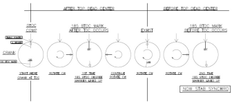
So yakesly and others... so I need to rotate my crank 1 1/2 turns and then stab the 1/2 moon shaped synchro BUT where does the 1/2 moon shape "face"? Do I use one of the alignment tools (for stabbing these) but which one?

1712899803583.png
 

frdboy

Contributor
Full Member
Joined
Jul 16, 2013
Messages
203
It's the simple stuff that drives ya NUT's. lol Simple job to press a new melonized gear on the synchronizer and 4 1/2 hrs later now the thing won't drop over the oil pump hex shaft. Done this countless times counting SBC's. (not counting my dealer days).
Since that shouldn't happen I tried my old one and it slides right in. Tried the new one again and zip.

Drug out a couple of Cleveland and Modified hex drive shafts from old stroker build& and they won't fit either.

GOTTA LOVE QUALITY NEW MOTORCRAFT PARTS. :(

Anyway, it all started when a simple pressing off + on of the new gear and the upper of the two tension pins on the shaft (not the gear one) bent enough that after a bunch of dinking around, driving to town for .125" tension/roll pins and making it all fit/work with the proper amount of play and I should have been done hours ago.

Here comes a couple pics of how the 3 different gears I have aren't close to being the same size. Sure don't want clearance issues. They ALL sit with the bottom of the gear at different measurements from the shaft AND the where the synch sits on the block deck... I shouldn't measure anything and just STICK STUFF TOGETHER! lol

So the super short video shows the gap when the upper of the two tension pins are bent from pressing a new gear on. I saw somebody earlier this week post a pic of a 1/4" gap between the upper cast pc and the machined pc with the upper pin. Pretty sure this was the result of pressing a new gear on and bending the upper pin.

Anyway, now I get to grind a file down so it's 5/16" wide and file down the inside of the hex shaft so I can stick a hex oil pump drive shaft in place.

That should only take a few hours.

Is the inside of the cam sync hardened? If so, I need to order a new one...another week.

Notice in the last Pic how the casting hole for the hex shaft isn't centered? Also gotta notice how the two pics with the dial calipers showing the appr center of the tension pin which locates the position of the gear are different by over .080" . I only measured this to get a reference because like I mentioned before, ALL the gears sit at different positions on the shaft & I'm assuming different positions on the teeth of the cam gear. Gotta love QC.


When you press the gear on you really need to be pressing against the shaft not the body of the housing, that is why the upper roll pins bent. I use a small socket on the shaft (kinda inside your half moon wheel) on the bottom to press against. That way there is no tension on anything but the shaft.

Have you confirmed it's the hex shaft that wont go in? I had one cam sync. I was building and the OD of the shaft below the dist. gear was too large not allowing the shaft to drop in. I chucked a 5/16 hex in a drill, slid the shaft on so I could spin it and used some emery paper to polish the OD down so it would fit.

Here is the spec. for where that gear needs to be and where to measure from
 

Attachments

  • PXL_20240412_104143491.jpg
    PXL_20240412_104143491.jpg
    427.5 KB · Views: 9

frdboy

Contributor
Full Member
Joined
Jul 16, 2013
Messages
203
So yakesly and others... so I need to rotate my crank 1 1/2 turns and then stab the 1/2 moon shaped synchro BUT where does the 1/2 moon shape "face"? Do I use one of the alignment tools (for stabbing these) but which one?

View attachment 923104


Using digital falling........ your 1/2 moon needs to be just exiting the sensor in the direction the dist. turns. (CCW) Just make sure you are 185* +/- 30* BTDC cyl 1 compression.
 

Attachments

  • PXL_20240412_105915404~2.jpg
    PXL_20240412_105915404~2.jpg
    253.2 KB · Views: 6
Top